Assign Footprints to Capacitors C2 and C3 and Choose Footprint For Capacitor C4
You can watch this video on Youtube by clicking on Kicad Tutorial 1.5 Part A: Choose and
Choose and Assign KiCad Footprint to Capacitor (2 C2 – 1000pF)
1. In our KiCad tutorial the next item in our list in the Assign Footprints window under
Symbol: Footprint Assignments is 2 C2 - 1000pF.
2. If we click on it, it shows up in red in Eeschema.
3. From the circuit diagram in Eeschema, we see that C2 is also a non- polarized
1000pF capacitor.
4. From the VISHAY VY2 series Capacitor datasheet, we see the following in
figure 1.5A below:
 |
| Fig. 1.5A: Vishay Datasheet |
5. From the datasheet above next to 1000pF we can see that:
5.1. Body Diameter Dmax. (mm) is given at 7.5 mm.
5.2. Body Thickness Tmax. (mm) is given as 5.0 mm.
5.3. Lead Spacing F (mm) is given as:
5.3.1. 5.0 mm.
5.3.2. 7.5 mm.
5.3.3. 10.0 mm.
5.3.4. 12.5 mm.
6. What this means once again though is that according to the KiCad footprint naming
convention the following disc capacitor KiCad footprints are possible depending on
the lead spacing:
6.1. Capacitor_THT: C_Disc_D7.5mm_W5.0mm_P5.00mm.
6.2. Capacitor_THT: C_Disc_D7.5mm_W5.0mm_P7.50mm.
6.3. Capacitor_THT: C_Disc_D7.5mm_W5.0mm_P10.00mm.
6.4. Capacitor_THT: C_Disc_D7.5mm_W5.0mm_P12.50mm.
7. It means any of the above KiCad footprints can be used.
8. The only difference between the footprints is the lead spacing which can be either
5.00mm, 7.50mm, 10.00mm or 12.50mm.
9. We can use exactly the same footprint we used before on the 100pF capacitor
that being: Capacitor_THT: C_Disc_D7.5mm_W5.0mm_P10.00mm
10. Choose as before and double click on:
Capacitor_THT: C_Disc_D7.5mm_W5.0mm_P10.00mm.
11. Click on Apply, Save Schematic & Continue.
12. The allocation of the footprint to capacitor C2 in the Assign Footprints window of
KiCad is shown in the figure below:
 |
| Assignment of footprint to capacitor C2 in the Assign Footprints window of KiCad |
13. If you click on the image above you will get an enlarged image and you will be able
to see it better.
Choose and Assign Footprint to Capacitor (3 C3 – 470pF)
Assignments is 3 C3 - 470pF.
2. If we click on it, it shows up in red in Eeschema C3 470pF non-polarized capacitor.
3. From the VISHAY datasheet above in figure 1.5A next to 470pF we once again
can see that:
3.1. Body Diameter Dmax. (mm) is given at 7.5 mm.
3.2. Body Thickness Tmax. (mm) is given as 5.0 mm.
3.3. Lead Spacing F (mm) is given as:
3.3.1. 5.0 mm.
3.2. 7.5 mm.
3.3. 10.0 mm.
3.4. 12.5 mm.
4. We can use exactly the same KiCad footprint we used before on the 100pF and
1000pF capacitors that being:
Capacitor_THT:C_Disc_D7.5mm_W5.0mm_P10.00mm
5. Choose as before and double click on:
Capacitor_THT: C_Disc_D7.5mm_W5.0mm_P10.00mm
6. Click on Apply, Save Schematic & Continue.
Choose Kicad Footprint for Capacitor (4 C4 – 0.1uF)
1. The next item in our list in the Assign Footprints window under Symbol:
Footprint Assignments is 4 C4 - 0.1uF or 100nF or 100 000pF.
2. If we click on it, it shows up in red in Eeschema as C4 0.1uF non-polarized capacitor.
4. Those capacitors only go to 10 nF.
5. We now use the VISHAY Lower Voltage Ceramic Single-layer DC Disc Capacitors
2 kVdc to 7.5 kVdc should do the trick.
6. On the 564R and 565R series capacitors Vishay Cera-Mite datasheet
we see the following in figure 1.5B:
 |
| Fig. 1.5B: Vishay Ceramic 0.1 uF Ceramic Capacitor |
7. Lower down the table with heading Y5V DIELECTRIC in figure 1.5C below we see
the 0.1 uF capacitor we are looking for.
 |
| Fig. 1.5C: Y5V Vishay Ceramic Capacitor |
8. In the VISHAY datasheet, we find also the dimensions shown in figure 1.5D below:
 |
| Fig. 1.5D: Dimensions Explained |
9. From this we can see the capacitor being a SIZE 15 has the following dimensions:
9.1 Dmax DIAMETER (mm) or D (in KiCad) = 24.1 mm.
9.2. Tmax THICKNESS (mm) or W (in KiCad) = 6.1mm.
9.3. LS LEAD SPACE (mm) or Pitch P (in KiCad) = 9.5mm.
10. The capacitor is basically disc-shaped therefore Disc
11. The capacitor is non-polarized therefore C.
12. In KiCad format the KiCad capacitor footprint, therefore, should look like this:
Capacitor_THT:C_Disc_D 24.1mm_W6.1mm_P9.50mm.
KiCad Footprint Editor
How To Save A Kicad Footprint Library And A Kicad Footprint
You can watch this video on YouTube by clicking on: Kicad Tutorial 1.5 Part B: How To Save
Kicad Footprint Library And Kicad Footprint.
Kicad Footprint Library And Kicad Footprint.
1. To open the KiCad Footprint Editor in Eeschema click on the Footprint Editor icon.
2. It is the icon with the horizontal IC and the green legs.
3. The Footprint Editor window opens as shown in figure 1.5D.1 below:
 |
| Fig, 1.5D.1 Footprint Editor |
4. In the left column, all the libraries appear.
5. These are the files with the .pretty extensions.
6. It is in these library files in which all the footprint files are kept.
7. The footprint files have .kicad_mod files.
8. You cannot store any footprints that you yourself create in the KiCad footprint library
files of KiCad that were installed when you downloaded KiCad.
9. As can be seen in the figure above the following are examples of KiCad
footprint libraries:
9.1. Fuse;
9.2. Inductor; and
9.3. Jumper.
10. If you click on the “+” of the Fuse library, you will see all the different types of Fuse
footprints listed beneath Fuse.
11. They are shown in the figure below 1.5D.2:
 |
| Fig. 1.5D.2 Fuse Library with Fuse Footprints |
12. These fuse footprints have .kicad_mod extensions although not shown in the
Footprint Editor in the figure 1.5D.2 above.
13. If you want to create and store your own footprint you have to create your own
KiCad footprint libraries.
14. As can be seen in figure 1.5D.3 below I opened a file right on my C-drive
called KICADFootprints.
 |
| Fig. 1.5D.3: Kicad Footprint files created on C-drive |
15. I am going to use this file to store and save my own KiCad footprint libraries
and footprints.
16. In the Footprints Editor by selecting File and clicking on New Library… and
then navigating to the KICADFootprints file I created libraries
shown below as: Capacitors.pretty.
17. As can be seen in figure 1.5D.3 I also created the following footprints and
saved then in the KICADFootprints file:
17.1. Test Foot Print.kicad_mod, and
17.2. TestFootPrint.kicad_mod.
18. If we look in the Footprint Editor we can see how these libraries and footprints
are displayed in the Footprint Editor.
19. Shown in figure 1.5D.4 below is the file KICADFootprints that contain the
footprints files named Test Foot Print and TestFootPrint.
 |
| Fig. 1.5D.4: Shown in Footprints Editor KICADFootprints File Containing Footprints Test Foot Print and TestFootPrint |
20. Going back to the files stored on my computer we see in figure 1.5D.5 below that
in the KICADFootprints file is stored the footprint library file Capacitors.pretty.
21. In the Capacitors.pretty library file is stored the footprint file TEST2.kicad_mod.
 |
| Fig. 1.5D.5: Capacitors.pretty footprint library file Contains TEST2.kicad_mod footprint file |
22. The corresponding the Capacitors.pretty library file with the footprint file
TEST2.kicad_mod in the Footprint Editor can be seen in figure 1.5D.6 below:
 |
| Fig. 1.5D.6: Capacitors footprint library having TEST2 footprint shown in Footprint Editor |
23. As can be seen in the figure above in the Footprint Editor the Capacitors footprint
library file contains the TEST2 footprint file.
24. The file extensions .pretty for Capacitors footprint library and the .kicad_mod for
the TEST2 footprint file are not shown in the Footprint Editor.
25. As a final check in Footprint Editor click on the Preferences menu and then
select Manage Symbol Libraries ... .
26. The Footprint Libraries window opens as shown in the figure 1.5D.7 below
 |
| Fig. 1.7D: Footprint Libraries Window |
27. Scroll to the end of the Global Libraries window.
28. The KICADFootprints file, as well as the Capacitors footprint
libraries with .pretty extensions are shown in the Footprint Libraries window.
Create a New KiCad Footprint for Capacitor
(THT: C_Disc_D24.1mm_W6.1mm_P9.5mm)
How To Create A Capacitor Footprint
You can view this video on Youtube by clicking on this link: How To Create A Kicad
Create Pad1
1. KiCad does not have this footprint:
Capacitor_THT:C_Disc_D 24.1mm_W6.1mm_P9.50mm.
2. We have to create a new KiCad capacitor footprint.
3. Open the Footprint Editor.
4. Click on New Footprint.
5. Enter the name Capacitor_THT_C_Disc_D 24.1mm_W6.1mm_P9.50mm.
6. Click on Add pad.
7. Pad 1 should be at y = - LS/2 = -9.5mm/2 = - 4.75mm and at
x = - LO/2 = -1.7mm/2 = - 0.85mm.
8. The WIRE SIZE (mm) is given to have a diameter of 0.64mm.
9. Let's give the hole in the pad a diameter 0.75mm and the overall diameter of the hole
1.750mm.
10. Right-click on pad1.
11. Choose Properties.
12. Then set the pad 1 properties up as shown in figure 1.5E below:
 |
| Fig. 1.5E: Pad1 of Capacitor C4 100nF Properties |
13. Click Save.
Create Pad2
1. Right-click on pad1.
2. Choose Duplicate.
3. Position the duplicate pad 1 below the horizontal X-axis.
4. Right-click duplicate pad1.
5. Choose Properties.
6. Set properties as shown in figure 1.5F below:
 |
| Fig. 1.5F: Properties of Pad 2 of Capacitor C4 |
7. Click Save.
Make The New KiCad Capacitor Footprint More Generic
1. The footprint of capacitor C4 100nF as it is at the moment is shown in figure 1.5G
below:
 |
| Fig. 1.5G: Footprint Capacitor C4 at the moment. |
2. We do not know whether this is the top or bottom view.
3. We can make the footprint more generic by adding another two pads.
4. Right-click on pad 1.
5. Select Duplicate.
6. Move the duplicated pad to the right of pad 1.
7. Right-click on the duplicated pad 1.
8. Select Properties.
9 Set the properties of the duplicated pad (now pad3) as in figure 1.5H below:
 |
| Fig, 1.5H: Properties of Pad3 |
11. Do the same for pad2.
12. Make a duplicate of pad2.
13. Move the duplicate to the left of pad2.
14. Set up the Properties (for pad4) as follows as shown in figure 1.5I below:
 |
| Fig. 1.5I: Pad4 for Capacitor C4 of 100nF. |
15. Click OK
16. The footprint so far should now look like shown in figure 1.5J:
 |
| Fig. 1.5J: Footprint of Capacitor so Far. |
17. We still have to do the outline of the new Kicad capacitor footprint.
Outline of New Capacitor Footprint C4 100nF
Dmax DIAMETER (mm) is 24.1mm.
2. We know that Tmax THICKNESS (mm) or width = 6.1mm.
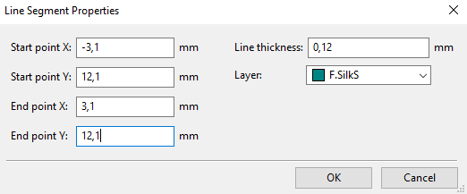
Draw Top Horizontal Line
and ends at x = 3.1 mm and y = -12.1mm.
2. Click on Add graphic line and draw a horizontal line.
3. Right-click on the horizontal line and set the Line Segment Properties as follows
as shown in figure 1.5K
 |
| Fig. 1.5K: Top Horizontal Line Properties of Outline of Capacitor C4 |
4. Click OK.
Add Bottom Horizontal Line
2. Select Duplicate.
3. Move the duplicated horizontal line to below the lower two pads.
4. Right-click on the bottom horizontal line and set the Line Segment Properties
as follows as shown in figure 1.5L below.
 |
| Fig. 1.5L: Bottom Horizontal Line of Outline of Capacitor C4 |
5. Click OK.
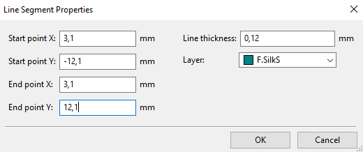
Draw the Left Vertical Line
1. Let’s draw the left vertical line so it starts at x = -3.1mm and y = -12.1 mm
and ends at x = - 3.1 mm and y = 12.1mm.
2. Click on Add graphic line and draw a horizontal line.
3. Right-click on the horizontal line and set the Line Segment Properties as
follows as shown in figure 1.5M.
 |
| Fig. 1.5M: Left Vertical Line Properties of Capacitor C4 |
4. Click OK.
Add Right Vertical Line
2. Select Duplicate.
3. Move the duplicated horizontal line to the right of the pads.
4. Right-click on the bottom horizontal line and set the Line Segment Properties
as follows as shown in figure 1.5N below:
 |
| Fig. 1.5N: Right Vertical Line Properties of Outline of Capacitor C4. |
5. Click OK.
6. Click Save.
7. The KiCad footprint of capacitor C4 is now finished and is shown in figure 1.5O below:
 |
| Fig. 1.5O: Finished Footprint of Capacitor C4. |
8. Click Save and click Close.
Assign Footprint To C4 And C5
You can watch this video on Youtube by clicking on this link:
How To Assign Capacitor Footprints: Kicad Tutorial 1.5 Part DAssign or Add KiCad Footprint Capacitor_THT_C_Disc_D
24.1mm_W6.1mm_P9.50mm to Capacitor (4 C4 – 0.1uF)
2. Click on Assign PCB footprints to schematic symbols.
3. The Assign Footprint window opens.
4. Under the middle window with the heading:
Symbol: Footprint Assignments see 4 C4- 0.1uF,
in the left window under Footprint Libraries scroll to where you
have saved the footprint, in my case, it is Capacitor, double click on it.
5. In the window on the right under Filtered Footprints the footprint you just created
should appear.
6. In my case it is:
“Capacitor:THT_C_Disc_D24.1mm_W6.1mmP9.50mm.”,
7. select, 4 C4- 0.1uF in the middle window.
8. Double click on:
“Capacitor:THT_C_Disc_D24.1mm_W6.1mmP9.50mm.”
to assign it to 4 C4- 0.1uF.
9. Click Apply, Save Schematic & Continue.
Assign or Add KiCad Footprint to (5 C5 – 200uF)
Footprint Assignments is 5 C5 – 200uF or 200 000nF.
2. If we click on it, it shows up in red in Eeschema.
3. This is a polarized capacitor.
4. So, we can use an electrolytic capacitor.
5. We will choose from the NIPPON CHEMI-CON Miniature Aluminum Electrolytic
Capacitors which look like this as shown in figure 1.5P below:
 |
| Fig. 1.5P: Nippon Electrolytic Capacitor |
6. We look further down the datasheet until we see as shown below in figure 1.5Q the
diameter of the 200 uF capacitor:
 |
| Fig. 1.5Q: Diameter of 200 uF Capacitor |
7. We see next to WV 100 (Vdc) and next to Cap (uF) in the 200-row, (for 200 uF) and in
the Case size (theta D x L (mm)) column is written 16x20.
8. This means the capacitor has a diameter or D (in KiCad format) of 16mm.
9. If we look a further upwards towards the top in the datasheet, we will see the
capacitor's legs have a pitch of 7.5 mm as indicated from figure 1.5R shown below:
 |
| Fig. 1.5R: Pitch of Capacitor |
10. From the above, we see that since the capacitor has a diameter of 16mm it has an
F = 7.5 mm or P (in KiCad) of 7.5mm.
11. From the all above we can thus say that as far as a footprint is concerned, we have:
11.1. a Capacitor;
11.2. that is THT or through-hole through;
11.3. that is CP or polarized;
11.4. it is Radial or has radial extending legs;
11.5. it has D or diameter of 16.0mm; and
11.6. it has P a leg pitch or spacing of the legs of 7.5mm.
12. Therefore, the footprint written in KiCad format looks like this:
Capacitor_THT:CP_Radial_D16.0mm_P7.50mm.
13. Choose as before and double click on
Capacitor_THT:CP_Radial_D16.0mm_P7.50mm.
14. Click on Apply, Save Schematic & Continue.
15. The footprint should look like this as shown in figure 1.5S below:
 |
| Fig. 1.5S: Footprint of Capacitor |
16. Click on the 3D Display icon it is the icon with a square component mounted in a
PCB board viewed from the side.
17. It should look like shown in figure 1.5T below:
 |
| Fig. 1.5T: 3D View of Capacitor |
18. Click on Apply, Save Schematic & Continue.
19. Click Save.
Let me know if I have made any mistakes.
Previous: Tutorial 1.4: Assign Footprints
Next: Tutorial 1.6: Assign More Footprints: Diode (6 D1 - MBR340)
No comments:
Post a Comment