Create or Design a Footprint for an Inductor (9 L1- 10uH)
You can watch this video on YouTube at: design inductor footprint kicad tutorial 1.8
10uH inductor.
2. The current in L1 the 1uH inductor is according to LTspice is shown in figure 1.8A
below in the light blue trace:
 |
| Fig. 1.8A: Inductor Current |
3. According to the light blue trace, the current in L1 the 1uH conductor starts a zero.
4. After about 0.05 milliseconds it starts to rise to a maximum of 5 amps.
5. After about 0.25 milliseconds it declines to zero amps after 0.275 milliseconds.
6. At approximately 0.285 milliseconds rises to a maximum of 2 amps at
0.3 milliseconds.
7. At 0.31 milliseconds it drops down a maximum of 1.5 amps and settles there.
8. The RMS value of the current over a period of 1 ms is 1.9844 A.
Suitable 10uH 5A 25 Milliohm Inductor (Wurth Electronics Inc. Part Number 7447710
2. It is an inductor with Digi-Key Part Number 732-1208-6-ND shown in the
figure 1.8B below:
 |
| Fig. 1.8B: 10 uH 5A Inductor From Wurth Electronics |
3. The inductor is from Wurth Electronics Inc.
4. It has part number 74477110 and is a 10 uH 5 A 25 milliohm inductor.
5. It has a unit price of $ 2.12.
6. The datasheet can be found at Wurth Electronik 74477110.
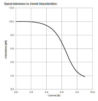
7. The inductance of the inductor compared to current is shown in figure 1.8C below:
 |
| Fig. 1.8C: Inductance v Current of 10uH Wurth Conductor |
8. As can be seen, the current is below 2 amps the inductance is at 10 uH.
9. As shown above, the current settles at a maximum of 1.5 amp.
10. This is what we want.
Footprint For Inductor (9 L1- 10uH)
1. From the datasheet the dimensions and land pattern or footprint are given as in
figure 1.8D below:
figure 1.8D below:
 |
| Fig. 1.8D: Footprint of 10uH Inductor |
Design Footprint For Inductor (9 L1- 10uH)
1. Open the Footprint Editor.
2. It is the icon which is a horizontal IC with green legs.3. In the Footprint Editor click on New Footprint
4. It is the icon which is a horizontal IC with green legs on the top left.
5. Enter footprint name: InductorWurthElectronics7447110.
6. Click OK.
7. To save footprint select digikey-footprints and click Save.
Add Upper Pad 1
1. Click on Add pad.
2. It is the green circle icon.
3. Right-click on the pad.
4. Select Properties.
5. The Pad Properties window opens.
6. Set:
6.1. Pad number: 1
6.2. Pad type: SMD
6.3. Shape: Rectangular
6.4 Position X: 0.0 mm.
6.5 Position Y: -4.95 mm. It is calculated by 7.0 mm/2 + 2.9 mm/2 = 3.5 mm +
1.45 mm = 4.95 mm. It is in the negative y-direction as it is above the
x-axis.
6.6. Size X: 5.4 mm.
6.7. Size Y: 2.9 mm.
7. The properties of the top pad pad1 should be as shown in figure 1.8E below:
 |
| Fig. 1.8E Pad 1 Properties Window |
8. Click OK.
Add Lower Pad 2
1. Right-click on pad1.
2. Select Duplicate.
3. Right-click on duplicated pad 1 and select Properties.
4. Set up pad 2 as in figure 1.8F below:
 |
| Fig. 1.8F: Properties of Lower Pad2 |
5. Click OK.
6. Use the Vernier Clamp Measure distance tool to make sure that the dimensions of
the two pads and the distance between the pads comply as set out in the
datasheet above.
Add Outline of Footprint for Inductor
Add Top Horizontal Line
2. It is the icon with 3 blue lines with green dots connecting them.
3. Select the line.
4. Right-click and select Properties … .
5. The Line Segment Properties window opens.
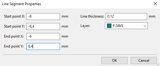
6. Set the properties as indicated in figure 1.8G below:
 |
| Fig. 1.8G: Top Horizontal Line Properties |
7. Click OK.
Add Bottom Horizontal Line
1. Right-click on the top horizontal line.
2. Select Duplicate.
3. Move duplicated line below pad 2.
4. Right-click on duplicated line.
5. Select Properties… .
6. Set up the properties as shown in figure 1.8H below.
 |
| Fig. 1.8H: Bottom Horizontal Line Properties |
7. Click OK.
Draw Vertical Lines
Draw Left Vertical Line
2. Draw the left vertical line on the left between two horizontal lines.
3. Select the vertical line and right-click.
4. Select Properties… .
5. Set the properties as shown in figure 1.8I below.
 |
| Fig. 1.8I: Left Vertical Line |
6. Click OK.
Draw Right Vertical Line
2. Draw the right vertical line on the left between two horizontal lines.
3. Select the right vertical line and right-click.
4. Select Properties… .
5. Set the properties as shown in figure 1.8J below:
 |
| Fig. 1.8J Right Vertical Line of Inductor Footprint |
7. Click OK.
8. Use the Vernier Clamp Measure distance tool to measure the distances of the
outline lines as set out in the datasheet above.
9. It should have a horizontal width of 12mm and a vertical height of 12.8mm.
10. Select “InductorWurthElectronics7447110” and “REF**” and move them to the top
and bottom of the outline.
11. Your inductor footprint should of the inductor from Wurth Electronics with part
number 7447110 now look like shown in figure 1.8K below:
 |
| Fig. 1.8K: Footprint of Inductor from Wurth Electronics Part number 7447110. |
13. Click Save.
Assign Footprint to Inductor (9 L1- 10uH)
2. It is the icon with the op-amp and horizontal IC in the lower right corner.
3. In the left column under Footprint Libraries click on digikey-footprints.
4. In the right column under Filtered Footprint scroll to digikey-footprints:
InductorWurthElectronics7447110.
5. In the Symbol: Footprint Assignments column select L1 10u.
6. Double-click on the footprint digikey-footprints:
InductorWurthElectronics7447110 and assign it to L1.
7. Click on View selected footprint.
8. You will see the inductor footprint as shown in figure 1.8K above.
9. Click OK.
Previous: Tutorial 1.7: Design Connector Footprint
Next: Tutorial 1.9: Assign Footprints to Resistors
Thank you
ReplyDeleteThis comment has been removed by a blog administrator.
ReplyDelete