The Circuit in LTspice
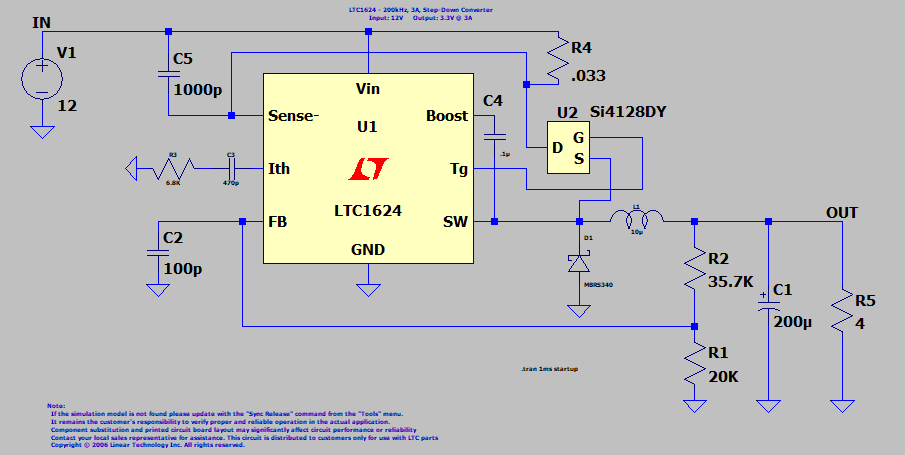 |
| Fig. 1.11A: Circuit In LTspice |
The Currents
1. The drain current in U2 Si4128Dy is as shown in by the light blue trace
figure 1.11B below:
 |
| Fig. 1.11B: Drain Current in Si128DY Over 1ms. |
2. The drain current in Si4128DY in the time period of (60 – 280)us is shown in
figure 1.11C below.
 |
| Fig. 1.11C: Drain Current During Time Period of (60 - 280)us. |
3. The RMS value of the drain current during the period of (60-280)us = 1.7001A.
4. The RMS value of the drain current in U2 over 1ms time period is 907.78mA as
shown in figure 1.11D below:
 |
| Fig. 1.11D: RMS Value of Drain Current of 1ms Time Period |
5. RMS Source current of U2 over a time period of 1ms = 907.66mA as shown in
figure 1.11E below:
 |
| Fig. 1.11E: Source Current U2 Over Time Period of 1ms |
6. The current in U1 LTC1624 pin SW up to 1ms = 63.165mA as shown in
figure 1.12F in the purple trace below:
 |
| Fig. 1.11F: Current in pin SW of U1 LTC1624 Over 1ms Time Period |
7. The current in inductor L1 is shown by the light blue trace in figure 1.11G below.
8. The RMS current in inductor l1 over a 1ms period = 1.9488A.
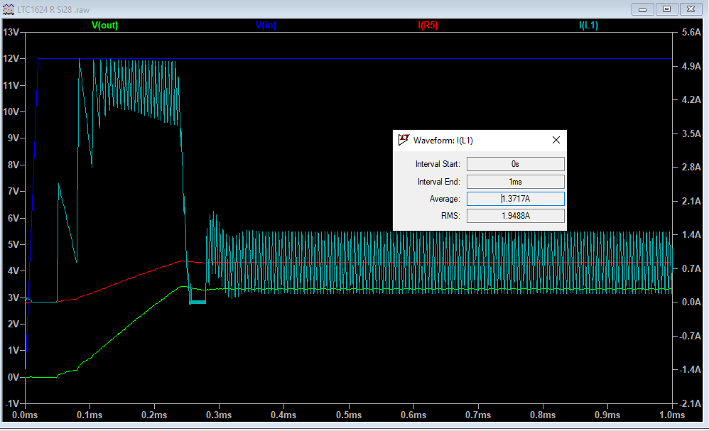 |
| Fig. 1.11G: Current in Inductor L1 Over 1ms Period |
9. The current in the trace or wire between R2 and C1 as in the LTspice circuit in
figure 1.11A above is shown in figure 1.11H below:
 |
| Fig. 1.11H: Current in Trace or Wire Between R2 and C1 |
10. The current between R2 and C1 has an RMS value of = 1.9488A.
11. From the above, we can conclude that the RMS value of the current does not
exceed 2A and reaches a peak value spikes of 6.4A over a period
of 280us - 60us = 220us.
Summary of Currents
A summary of current calculations from previous tutorials are shown in table 1.11A below:
 |
| Table 1.11A: Summary of Previous Current Calculations |
A further summary of current calculations are shown in table 1.11B below:
 |
| Table 1.11B: Further Summary of Previous Current Calculations |
KiCad Eeschema Circuit
The KiCad Eeschema circuit is shown for ease of reference in figure 1.11I below:
 |
| Fig. 1.11I: KiCad Eeschema Circuit |
Input Current
1. The input current in the conductor between IN pin V1 and capacitor C5 1000p in
the LTspice circuit is shown by the light blue trace in figure 1.11J below:
 |
| Fig. 1.11J: Conductor between IN pin V1 and capacitor C5 1000p Over Time Period of 1ms |
2. As can be seen from above the input current in the conductor between IN pin V1
and capacitor C5 1000p over a time period of 1ms is 907.73mA
3. The input current in the conductor between pin V1 IN and capacitor C5 1000p over
a time period of 40us and 280us is shown by the light blue trace in figure 1.11K below:
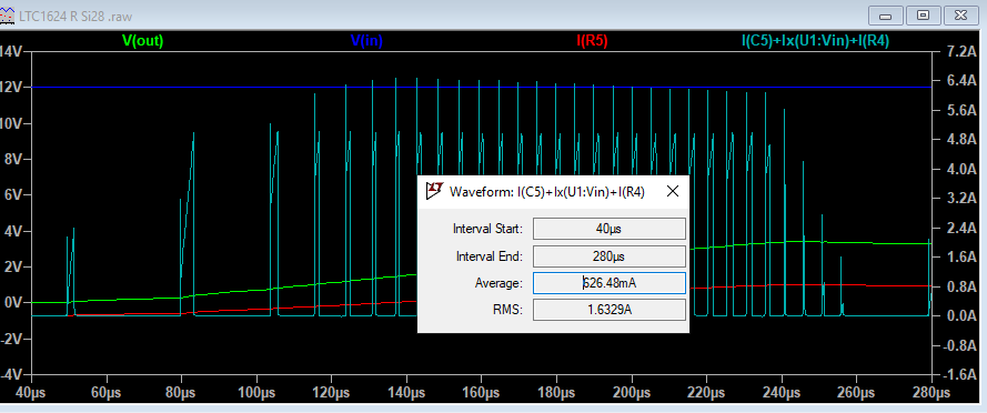 |
| Fig. 1.11K: Current In Conductor between pin V1 IN and capacitor C5 1000p Over Time Period 40us - 280us |
4. The RMS value of the current is 1.6329A.
5. The results over 1ms period of 907.73mA are tabulated in table 1.11C below:
 |
| Table 1.11C: Input Current Pin V1 of IN Over 1ms Period |
LTspice Capacitor C5
1. The current in the
LTspice circuit in capacitor C5 1000p over 1ms period is shown
in the purple
trace in the figure below:
 |
| Fig. 1.11L: Current in LTspice Capacitor C5 |
2. The current in capacitor
C5 1000p over 1ms period is 3.404mA
3. Capacitor C5 1000p in
LTspice is C2 1000pF in KiCad Eeschema.
Conductor LTspice Capacitor C5 1000p and pin Sense- of U1 LTC1624 and R4 .033
1. The current in the
LTspice circuit in the lower conductor between C5 1000p and
pin Sense- of U1
LTC1624 and R4 .033 is shown by the light blue trace in
figure 1.11M below:
 |
| Fig. 1.11M: conductor between LTspice Circuit C5 1000p and pin Sense- of U1 LTC1624 and R4 .033 |
2. As can be seen, it is
described as I(R4)+Ix(U2D) by the LTspice software and is
written in light blue
at the top of the graph in the figure above.
3. It is the current in R4 .033 and
Drain current U of U2 Si4128DY.
4. It is in total 3.43mA.
5. In KiCad Eeschema
it is the current in the lower top horizontal conductor between
pin 1 ISENSE of
U1 LTC1624CSB and Drain current pins 5, 6, 7, 8 of U2
SI4128DY_T1-GE3.
LTspice Pin Vin of U1 LTC1624
1. In the LTspice circuit
the current flows into pin Vin of U1 LTC1624 is shown in the
light blue trace
in figure 1.11N below:
 |
| Fig. 1.11N: Current flowing Into Pin Vin of U1 LTC1624 |
2. This current is 6.4948mA.
3. In the KiCad Eeschema
circuit, it is the current that flows into
pin 8 VIN of U1 LTC1624CSB.
4. A summary of the currents calculated above by LTspice are shown in table 1.11D below:
 |
| Table 1.11D |
Current In LTspice Circuit Capacitor C2 100p
the figure below:
 |
| Fig. 1.11O: Current In Capacitor C2 100p in LTspice Circuit |
2. In the LTspice circuit the current in capacitor C2 100p is 354.8nA.
3. In KiCad Eeschema it is capacitor C1 100pF.
Current In Capacitor C4 0.1u In LTspice Circuit
1. In the LTspice circuit
the current in capacitor C4 0.1u is shown in the light blue trace
in
figure 1.11P below:
 |
| Fig. 1.11P: Current in Capacitor C4 0.1uF in LTspice Circuit |
2. The current is 54.69mA.
3. In KiCad Eeschema it is referred to as C4 0.1uF.
The Current In Diode D1 MBRS340 In The LTspice Circuit
1. The current in the
LTspice circuit in diode D1 MBRS340 is shown in the light blue
trace in figure 1.11Q below:
 |
| Fig. 1.11Q: Current In Diode D1 MBRS230 In LTspice Circuit |
2. Current in the diode D1 MBRS340 is 1.7209A.
3. The Kicad Eeschema diode is referred to as D1 MBRS340.
Current In The Conductor Between Pin Tg of U1 LTC1624 And Pin G of U2 Si4128DY
1. In the LTspice circuit the current in
the conductor between pin Tg of U1 LTC1624
and pin G of U2 Si4128DY is shown by
the light blue trace in figure 1.11R below:
 |
| Fig. 1.11R: Current Between Pin Tg of U1 LTC1624 and Pin G of U2 Si4128Dy |
3. In the LTspice circuit
the current between pin Tg of U1 LTC1624 and pin G of U2
Si4128DY is 14.396mA.
4. In the Kicad Eeschema circuit the conductor is between pin 6 TG of U1 LTC1624CSB
and pin 4 Gate of U2 SI4128DY-T1-G3.
5. Summary of calculations done above are summarized as follows in table 1.11E below:
 |
| Table 1.11E |
Current In The Conductor In LTspice Circuit Between Pin FB of U1 LTC1624
And R2 35.7K And R1 20K
1. The current in the conductor in LTspice Circuit between pin FB of U1 LTC1624 and
R2 35.7K and R1 20K is shown in the light blue trace in figure 1.11S below:
 |
Fig. 1.11S: Current In The Conductor Between Pin FB of U1 LTC1624 and R2 35.7K and R1 20K
|
2. The current in the conductor in the LTspice circuit between pin FB of U1 LTC1624
and R2 35.7K and R1 20K is 374.34nA.
3. The KiCad Eeschema description of this conductor is the conductor between
pin 3 SET of U1 LTC1624CSB and R2 35.7k and R3 20k.
Current In Capacitor C1 200u In The LTspice Circuit
1. The current in
capacitor C1 200u in the LTspice circuit is shown in the light blue
trace
in figure 1.11R below:
 |
| Fig. 1.11R: Current In Capacitor C1 200u In LTspice Circuit |
2. The current in
capacitor C1 200u in LTspice circuit is 1.627A.
3. The KiCad Eeschema
description of this capacitor is C5 200uF.
4. The calculations done above are tabulated in table 1.11F:
 |
| Table 1.11F |
KiCad Eeschema Circuit With All The Relevant Currents
The KiCad Eeschema
circuit with all the relevant currents is shown in figure 1.11S below:
 |
| Fig. 1.11S: KiCad Eeaschema Circuit With Currents Indicated |
Conclusion
From the above we can
classify the currents into two groups:
1. Currents that range
from 354.8nA to 63.165mA and are below 100mA; and
2. Currents that range
from 671.75mA to 1.9488A
and are below 2A.
No comments:
Post a Comment