Trace Width Calculator
1. There are several track width calculators available.
2. There is the one at Advanced Circuits which you can reach by clicking
on the printed circuit width tool.
3. For Inputs: let's select the following:
3.1 Current 2 Amps
3.2 Thickness 1 oz/ft^2. This is very curious. However one of the units that track
thickness is measured in is once per square foot. That is you take a once of
the copper material the trace is made of and roll it out in one square foot you
get the thickness of the trace. Who has the time to do that?
3.3 Temperature Rise 10 Deg C.
3.4 Ambient Temperature 25 Deg C.
3.5 Trace Length 1 inch.
4. You should see the trace width calculator and results of Advanced Circuits as shown
in figure 1.12A below:
in figure 1.12A below:
 |
| Fig. 1.12A: Trace Width Calculator With Results From Advanced Circuits |
5. Our board is simple as it has only two front and back external layers in the air.
6. It has no internal layer and the results for internal layers can be ignored.
7. From figure 1.12A above the Required Trace Width is estimated at 30.8 mil.
8. The results are based on the equations from IPC-2221 as shown in figure 1.12B
below:
 |
| Fig. 1.12B: Equations For Calculation Of Trace Width Based On IPC-2221 Curves |
9. KiCad 5.1.2 also has a trace width calculator.
10. Click on the PCB Calculator it has a calculator as an icon.
11. Now click on the Track Width tab.
12. Set the:
12.1 Current: 2 A.
12.2 Temperature rise: 10.0 deg C.
12.3 Conductor length: 1 inch.
12.4 Trace thickness: 1 oz/ft^2.
13. The calculated Trace width: 31,3019 mil as shown in figure 1.12C below:
14. It is about the same as in the Advanced Circuits trace width calculation at 30.8 mil.
28. You should see the following in the figure 1.12E below:10. Click on the PCB Calculator it has a calculator as an icon.
11. Now click on the Track Width tab.
12. Set the:
12.1 Current: 2 A.
12.2 Temperature rise: 10.0 deg C.
12.3 Conductor length: 1 inch.
12.4 Trace thickness: 1 oz/ft^2.
13. The calculated Trace width: 31,3019 mil as shown in figure 1.12C below:
 |
| Fig. 1.12C: KiCad Trace Width Calculator. |
14. It is about the same as in the Advanced Circuits trace width calculation at 30.8 mil.
15. Go to Saturn PCB Design Inc on the internet.
16. Download their Saturn PCB Design Toolkit.
17. You can reach the toolkit by clicking Saturn PCB Design Toolkit.
18. Download and open the toolkit.
19. Click on the Conductor Properties tab.
20. If you cannot activate the selection button next to Conductor Width click on
the Tools menu above.
21. Select Program Options.
22. Select IPC-2152 without modifiers as shown in figure 1.12D below:
 |
| Fig. 1.12D: Program Options IPC-2152 without modifiers. |
23. Click Close.
24. In the Conductor Properties box set
24.1 Solve For: Conductor Width.
24.2 Conductor Current: 2 Amps.
24.3 Conductor Length: 1000mils.
24.4 Frequency: 1 MHz.
25. In the Options box set Base Copper Weight to 1oz.
24.3 Conductor Length: 1000mils.
24.4 Frequency: 1 MHz.
25. In the Options box set Base Copper Weight to 1oz.
26. In the Plating Thickness box chose Bare PCB.
27. Click Solve!
27. Click Solve!
 |
| Fig. 1.12E: Trace or Conductor Width IPC-2152 without modifiers. |
29. The conductor width is given as 80.1736 mils.
30. Select Program Options.
30. Select Program Options.
31. Select IPC-2221A as shown in figure 1.12F below:
 |
| Fig. 1.12F: IPC-2221A Selected. |
32. Click Close.
33. With the same settings as before, calculate the conductor width.
34. You should see the results as shown in figure 1.12G below:
 |
| Fig. 1.12G: Conductor Width Calculation With IPC-2221A |
35. This time the conductor width is given as 31.6808 mils.
36. Select Program Options.
37. Select IPC-2221A as shown in figure 1.12H below:
 |
| Fig. 1.12H Setting Conductor Calculation to IPC-2152 with modifiers |
38. Now the Conductor Width is disabled in the Solve For box.
39. We only have Amperage.
40. Type in the Conductor Width input box several values until the result in
the Conductor Current output box is close to 2 Amps.
41. In the end, a conductor width of 45 mils seemed to work see figure 1.12I below:
 |
| Fig. 1.12I: Trace Width Calculated With IPC-2152 with modifiers mode. |
Click on Help and then Help Topics in the Saturn PCB Design toolkit. They state the following:
"IPC Version:
The user can select the IPC version to use for current calculations.
We recommend using the IPC-2152 without modifiers for most applications.
The modifiers can be used when the user needs to minimize the conductor width as much as possible due to spacing constraints."
We recommend using the IPC-2152 without modifiers for most applications.
The modifiers can be used when the user needs to minimize the conductor width as much as possible due to spacing constraints."
Pad Width of MOSFET Si4128DY and Switching Regulator LTC1624
1. The pad width of MOSFET transistor Si4128Dy is 22.5 mils.
2. The pad width of the switching regulator LTC1624 is 24.5 mils.
2oz Track or Trace Thickness
Remember in tutorial 1.11 we grouped the conductors or track or trace thickness in
two groups a below 2A current group and a below 100mA current group.
Below 2A Current Group
1. If we accept a 12-degree Celsius increase in heat and choose a 2oz track or
2. See the calculations done with the Saturn PCB toolkit in figure 1.12J below:
 |
| Fig. 1.12J: Conductor Width Calculation 22mils Conductor Thickness 2oz and 12 Degree Celsius at 2A |
3. As can be seen, the conductor current calculated is 2.0132 A using IPC-2152
with modifiers.
Below 100mA Current Group
1. Setting the temperature increase to 10-degree Celsius increase and using a
2. See the calculations done with the Saturn PCB toolkit in figure 1.12K below:
 |
| Fig. 1.12K: Conductor Width Calculation 4 mils With Conductor Thickness 2oz and 10 Degree Celsius at 0.3378A |
As can be seen, the conductor current calculated is 0.3378 A using IPC-2152
with modifiers.
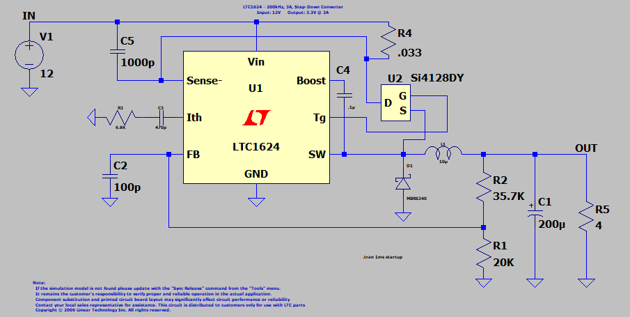
Eeschema Circuit With Currents Indicated
An Eeschema circuit with currents indicated as shown in figure 1.11L below:
 |
| Fig, 1.12L: Eeschema Circuit With Currents Indicated |