We would like to see how our printed circuit board (PCB) looks when we
have all the components mounted on the printed circuit board.
This is not necessary to have the printed circuit board made.
It is not part of the PCB maufacturig process.
It however does give us an idea of the dimensions once all the components are mounted.
It is also helpful if we want to import the 3d model of the PCB into other CAD software.
The 3d model of a component is represented by a Step file.
It has a .step or .stp file extension.
If our component does not have a 3d model we can import the Step file representing
the 3d model from the internet.
Open 3D Viewer
1. Open Pcbnew.
2. On the top menu click View and then select 3D Viewer.
3. The 3D Viewer window opens.
4. It shows a 3D view of the printed circuit board as show in figure 1.17A below.
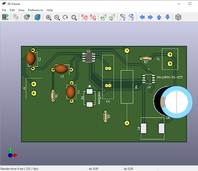 |
Fig. 1.17A: 3D View Of Printed Circuit Board |
5.  As can be seen there is no 3d model for inductor L1.


Import External 3D model for an Inductor
1.   The inductor L1 we choose in tutorial 1.8 Create Footprint for Inductor.
2. In the end we found a suitable inductor on the Digi-Key website with
Digi-Key part number 732-1208-2-ND – for tape & reel (TR) the and the
following particulars:
Manufacturer Würth Elektronik
Manufacturer Product Numer 74477110
Supplier Würth Elektronik
3. On the Digi-Key website we scroll down.
4. We see Step files are available at “Mfg CAD Models WE-PD-1260.stp” as in
figure 1.17B below.
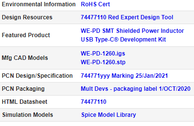 |
Fig. 1.17B: Step Files Available At “Mfg CAD Models WE-PD-1260.stp” |
5. So to download the Step files for the 3d model of the inductor L1 manufactured
by Würth Elektronik with manufacturer number 74477110 click on “WE-PD-1260.stp”.
6. The file “74477110_Download_WE-PD_1260_STP_rev1.stp” downloaded.
7. I copied and stored it on my computer and renamed the L1 inductor 3d file to have
         a shorter name “74477110_6A.stp”

8.     Other sites that may also contain 3d model component Step files are:
8.1. The manufacturer of the components’ website,
8.2. GrabCAD,
8.3. SnapEDA,
8.4. 3DContentCentral, and
8.5. Ultralibrarian.
9. In Pcbnew select the L1 inductor footprint.
10. Right-click on it and select Properties.
11. The Footprint Properties window opens.
12. Select the 3D Settings tab.
13. The 3D Settings window opens and is as show in figure 1.17C below.
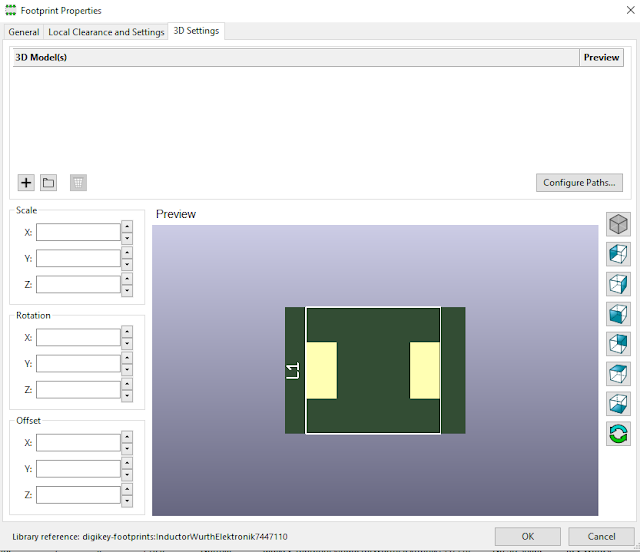 |
Figure 1.17C: Footprint Properties and 3D Settings Tab |
14. Click on the box with the folder.
15. Navigate to where you stored your L1 inductor 3d model Step file.
16. Select the Step file.
17. L1 inductor 3d model image should appear as in figure 1.17D below.
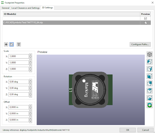 |
Figure 1.17D: 3D Model of L1 Inductor. |
18. Click OK.
19. In Pcbnew in the top menu click View and then select 3D Viewer.
20. The 3D Viewer window opens.
21. It shows a 3D view of the printed circuit board as show in figure 1.17E below.
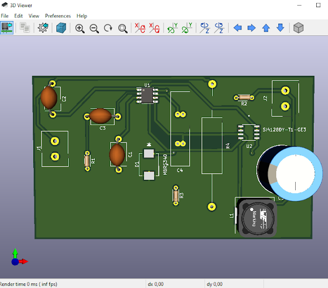 |
Figure 1.17E: 3D View of PCB with 3D Model of Inductor L1. |
22. The PCB now contains a 3d model of the inductor L1.
23. Close 3D viewer.
24.   Click Save.

Let me know if I have made a mistake.
Do not hesitate to leave any comment below.


